US Patent

The world's only 3-D Diaphragm TM

Send inquiries to: info@planotspeaker.com

Structure of one implementation of the Planot driver
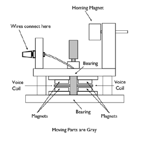
The top figure shows a cut away, side view, of a motor. The rotor (in gray) comprises the moving parts. It includes the spindle to which are mounted the bearings and the voice coils. This type of motor, a rotary voice coil swing arm actuator, is employed in hard drives to position the heads and also in scientific instruments. Its operating parameters are well understood.
The left figure shows a side view of one possible type of Planot driver. The vertical diaphragm would have a triangular cross section and be attached to bearings at both the top and bottom of the diaphragm.
The separate modules, base and motor and diaphragm, are unified into a single unit by the frame. The frame is composed of the top support arm and the bottom support arm and joined by the mast.
In this type of Planot driver there are two opposed voice coils to balance inertial forces (instead of the one a hard drive has). The motor frame serves as a support for the magnet structures. The motor frame is fixed to the bottom support arm.
(A structure should be attached to the open sides of the motor frame to allow air circulation for cooling of the voice coils but at the same time preventing particulate matter, especially ferrous material, from being drawn into the inside of the motor frame and to block sound generated by the rotor.) The motor can by itself generate significant sound and must be controled.
Attached to the top of support mast is the top support arm. The end of the arm holds the bearing at the top of the diaphragm. The rigid structure created by the mast, the support arms and the base creates a rigid support for the diaphragm and motor.
A large homing magnet is held in place by a bracket and is attached to the motor frame. A small homing magnet is placed on the side(s) of the diaphragm (or rotor) and whose pole faces the same pole of the large homing magnet. This Magnetic structure keeps the diaphragm & voice coil assemble centered in the magnets and provides dampening to the moving parts.
A set of four feet are fixed to the underside of the base to prevent the base from moving due to the inertial forces generated by the voice coil and diaphragm assemblies as they pivot.
The electrical signal from the audio amplifier (not shown) is fed to the voice coils by means of a speaker cable attached at the speaker wires connectors.
The electrical signal varies in frequency and amplitude. This signal causes a likewise varying magnetic field to be generated in the voice coils which interacts with the static magnetic fields of the permanent magnets to move the diaphragm that the voice coils are rigidly attached to.
When moved by the voice coils, the diaphragm pivots, creating planar pressure waves, and reproduces the amplitude and frequency information contained in the electrical signal.
When the diaphragm pivots it creates positive sound pressure as a because of the unique geometry of the diaphragm. The whole surface of the sides pushes equally against the surrounding air.

It Works
Support Arm
Mast
Diaphragm
Motor
Base

P4 Plot in Listening Room